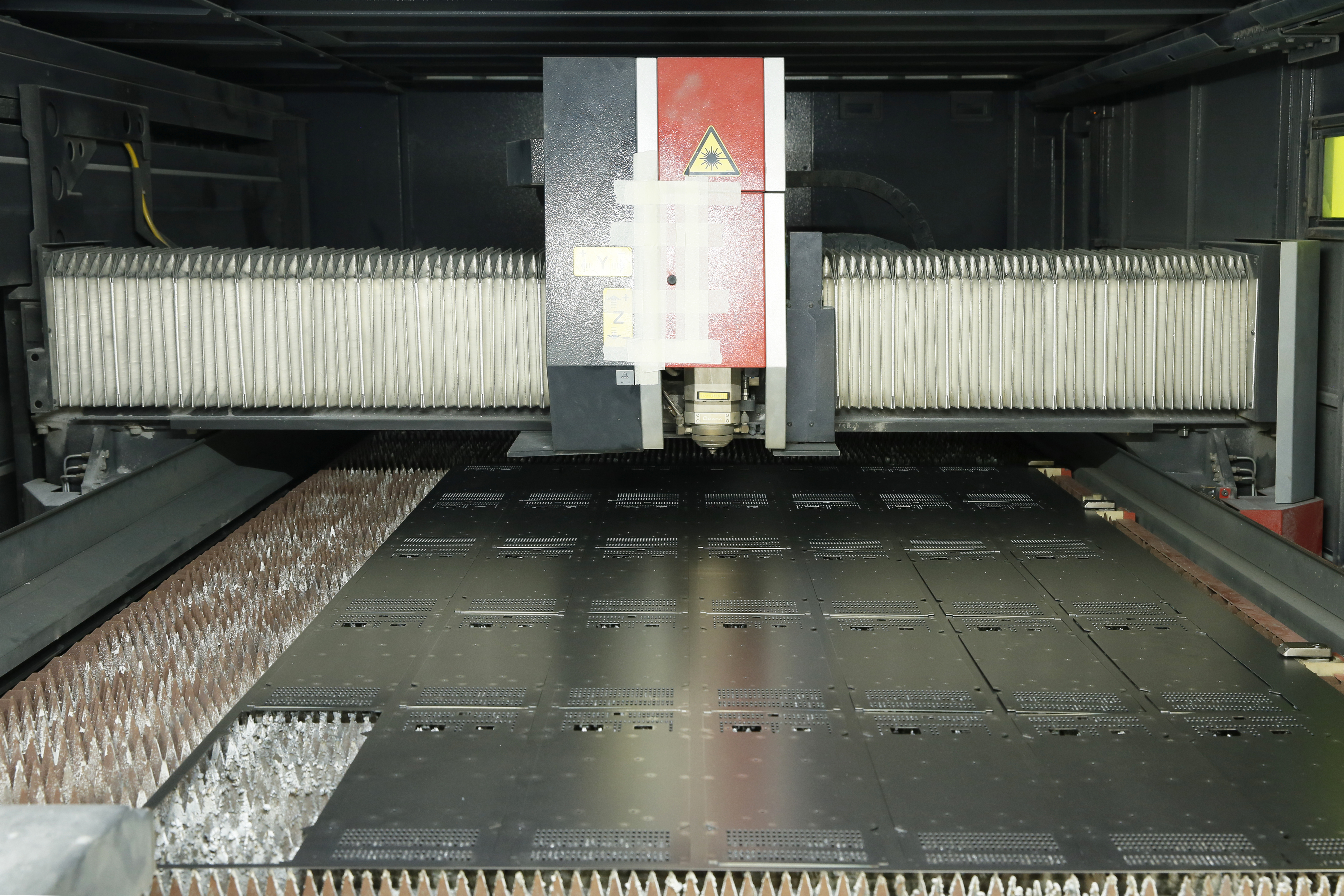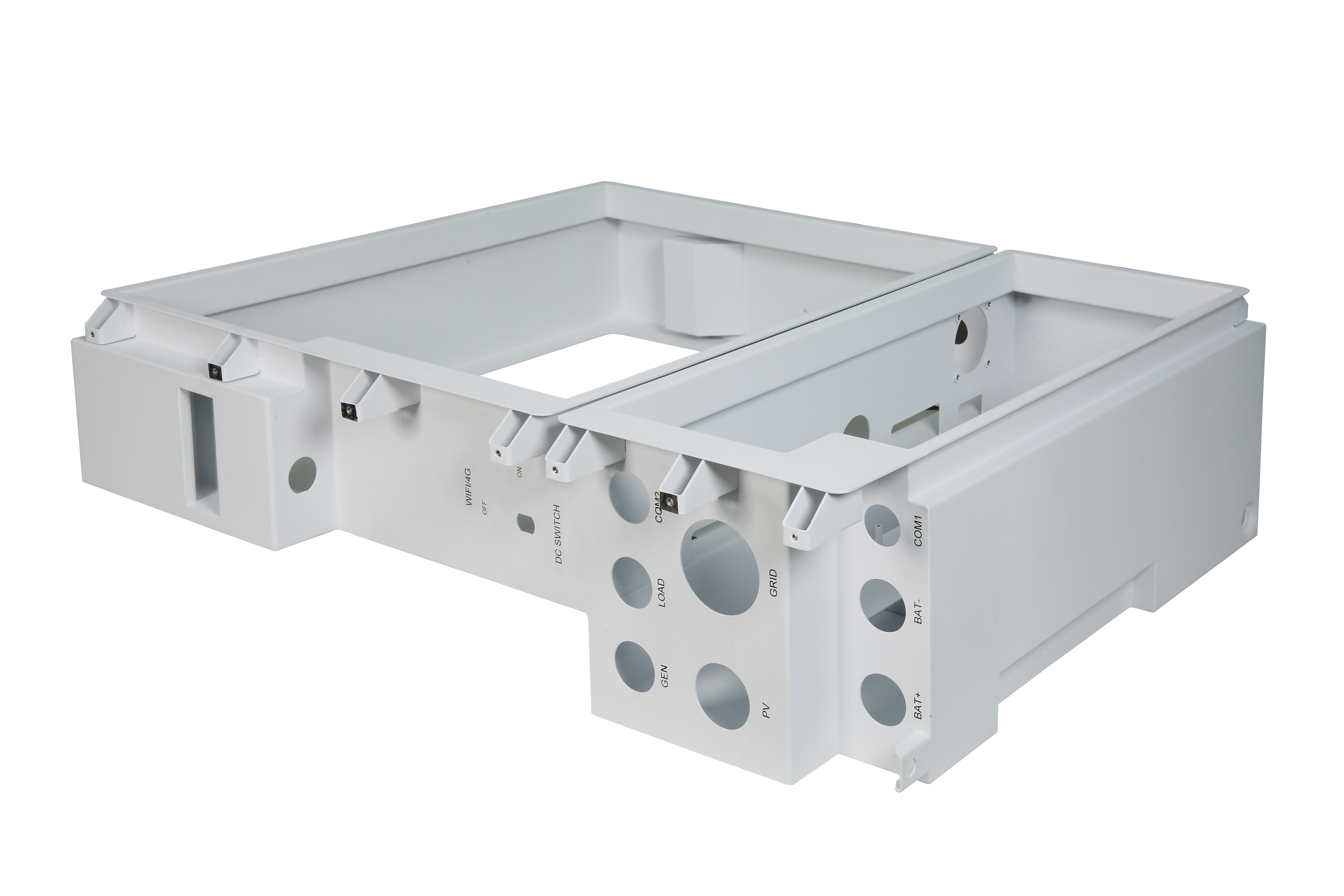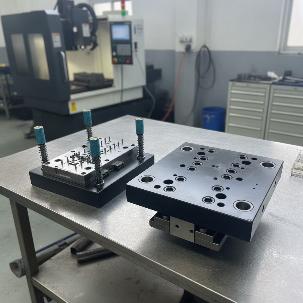
When planning serial production for formed sheet metal components, the decision to invest in progressive stamping dies for metal parts usually hinges on volume, geometry, and cycle time. Unlike single-stage transfer setups or secondary-operation punch tooling, a progressive die performs multiple distinct operations—such as piercing, notching, coining, and bending—along a continuously fed strip of metal during each press stroke. The payoff is immediate: once tuned, these dies yield finished parts at high stroke rates with minimal operator intervention. However, getting to that steady state requires a candid understanding of die construction, strip dynamics, and the heavy tooling sub-assemblies that keep critical clearances aligned under hundreds of tons of repeated impact.
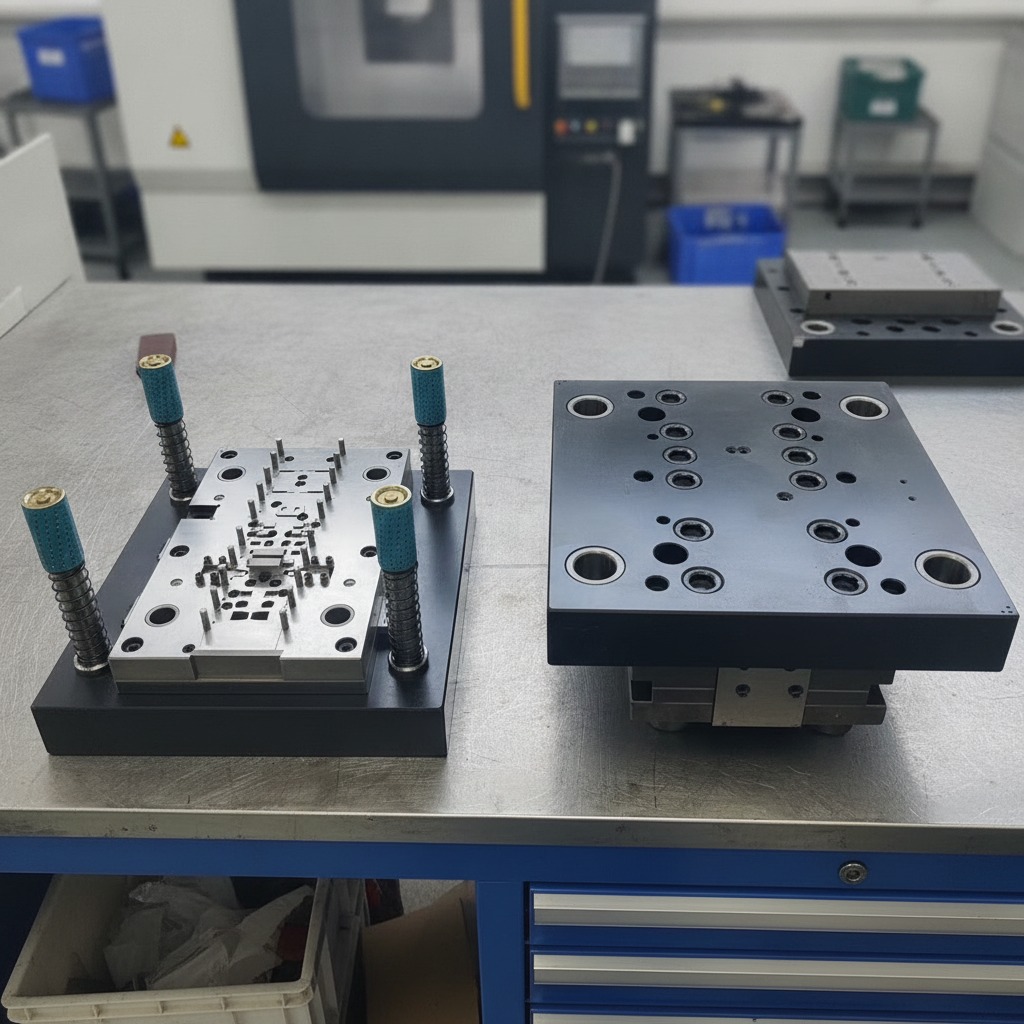
The Anatomy of Heavy Die Plate Assemblies
To an outside observer walking the toolroom floor, a disassembled progressive die looks like an intimidating stack of thick, precision-machined steel blocks. In practice, the upper and lower die sets act as rigid chassis that maintain micro-level clearances between punches and die cavities across thousands of strokes per hour.
Typical tooling assemblies consist of heavy rectangular base plates mounted with specialized functional plates: die shoes, punch plates, stripper plates, and stop blocks. On the lower shoe, one frequently encounters ground working surfaces populated by dozens of bored holes, clearance cutouts for scrap evacuation, and hardened dowel pins for repeatable locating. Opposite this assembly, corresponding plates carry precision-fitted circular bushings and wear sleeves designed to engage matching guide pillars. Many toolrooms also incorporate dedicated handling accessories—such as heavy corner posts with ergonomic or colored safety grips—to ensure the upper and lower halves can be safely separated, rigged, and handled by crane operators during maintenance or setup on the press bed.
These plates do far more than simply hold punches in place. Every bore, pocket, and fitted insert serves a specific locating or structural role. The alignment of these sub-plates dictates whether punch-to-die clearance remains uniform across all stations or shifts enough to cause premature burring, edge rolling, or fractured tooling components.
Progression and Strip Layout: Where Tooling Economics Are Decided
A progressive die is only as reliable as its strip layout. Before steel is ordered or plate milling begins, tool designers must determine the exact sequence of cuts and forms required to turn raw coiled stock into a finished component. This engineering phase represents the true margin between a smooth-running tool and an ongoing maintenance headache.
- Carrier Design: The strip must carry the partially formed workpiece cleanly from the infeed station to the final cutoff without twisting, stretching, or binding in the stock lifters. Whether using center carriers, dual-edge carriers, or flexible stretch webs, the carrier must absorb the mechanical stress of intermediate forming stages.
- Pilot Pin Locating: Because mechanical coil feeders introduce slight pitch variations over continuous cycles, pilot holes pierced in the very first station ensure micro-accurate part positioning before punches strike downstream. Pilot pins seat into these holes on every downstroke, physically centering the strip.
- Balanced Cutting Forces: A common pitfall in progressive tool engineering is clustering heavy notching or thick-gauge punching entirely on one end of the die shoe. Uneven tonnage across the die centerline introduces tipping moments (angular deflection) in the press ram, accelerating guide bushing wear and causing uneven edge shearing.
Modular Inserts versus Solid Die Blocks
Historically, low-to-medium volume progressive tools often featured large, solid die sections containing multiple stations in a single block. While cheaper to rough out initially, this architecture carries steep operational risks: a single broken punch or chipped cutting edge can sideline the entire tool, requiring extensive EDM or regrinding work that halts production for days.
Modern precision progressive stamping dies for metal parts lean heavily toward modular tooling designs. High-wear cutting areas, forming radii, and pilot holes are typically resolved into discrete, fitted circular or rectangular inserts seated directly into hardened pocket cavities. When an insert chips or reaches its wear limit, the maintenance crew unbolts that isolated station, drops in a pre-ground spare, and returns the tool to the press within hours rather than shifts.
For stamping buyers and process engineers, this modularity should be a direct specification checkpoint. If a supplier quotes a lower upfront cost for a solid-block die, remember to calculate the downtime cost when that tool inevitably requires off-line resharpening during an expedited production run.
Key Sourcing Verification: What to Review Before Tool Build
Commissioning custom progressive tooling requires tight coordination between your internal part designers and the external toolmaker. Before authorizing tool steel procurement or CNC roughing, verify the following parameters:
| Parameter | Design Consideration | Risk of Neglect |
|---|---|---|
| Shut Height & Stroke Length | Confirm die assembly fits specific press envelope and leaves clearance for stock lifters. | Tool cannot run on target press line without expensive sub-bolster rework. |
| Slug Evacuation Geometry | Ensure relief angles and vacuum assists prevent slugs from pulling up onto strip. | Slug denting on critical cosmetic surfaces; catastrophic punch breakage. |
| Material Grain Direction | Align severe 90-degree bend axes perpendicular to coil rolling direction where feasible. | Stress cracking along bend radiuses under nominal service loads. |
| Guide Post & Bushing Class | Specify ball-bearing or demountable plain bronze-plated bushings depending on stroke velocity. | Guide seizure or play-induced shearing damage at high cycle rates. |
Operational Pitfalls on the Shop Floor
Even a meticulously built progressive die can fail if press parameters and ancillary feeding equipment are out of step. In many cases, problems blamed on poor tool steel heat-treating actually stem from subtle mechanical interferences.
Slug pulling is arguably the most common disruption in high-speed sheet stamping. When cutting clearances are slightly wide or oil viscosity creates suction between punch faces and punched blanks, slugs can pull upward onto the die surface. On the subsequent stroke, the slug is hammered into the strip stock, damaging punch faces and marring the finished metal part. Integrating shear-angle punch tips, pneumatic slug suckers, or ejector pins is vastly easier during die construction than retrofitting them after tool sign-off.
Another recurring issue is misfeed detection. Without sensor probes or fiber-optic sensors watching the carrier strip pitch and verifying part progression, a coil jam will cause a hard double-strike—often buckling the strip, galling guide channels, and shearing precision dowel pins across multiple stations simultaneously.
Frequently Asked Questions
When should a project transition from stage tooling to progressive stamping dies for metal parts?
Typically, the crossover point occurs when annual part volumes exceed 25,000 to 50,000 units, or when tight positional tolerances between multiple holes and formed tabs make manual re-clamping across multiple presses impractical. If part geometry demands continuous handling that creates part-to-part variation, progressive tooling eliminates human handling error entirely.
What information does a toolmaker need to provide an accurate tooling quote?
Beyond standard 3D CAD files and 2D engineering drawings with geometric dimensioning and tolerancing (GD&T), you should provide the raw material alloy and temper, expected annual volume, target batch sizes, press bed dimensions, and shut height requirements. If you have specific requirements for nitrogen gas spring brands, standard guide pin types, or interchangeable insert configurations, state them upfront.
Can progressive dies handle high-strength steels or thick gauges?
Yes, but high-strength low-alloy (HSLA) steels and stock thicknesses exceeding 3 mm impose significantly higher snap-through shock loads on die assemblies. In these cases, heavy-section die shoes, reinforced guide pillars, and advanced surface coatings on cutting components are mandatory to resist deflection and early micro-fracturing.
Moving from Design to Part Sampling
Progressive tooling is an upfront capital commitment that determines your long-term unit production cost. Success requires treating the toolmaker as an active engineering collaborator rather than a passive print-reader. Provide realistic part tolerances, review the strip progression layout critically prior to tool steel cutting, and require full dry-cycle and first-article dimension reports under realistic press speeds before releasing the die set for full-scale production runs.