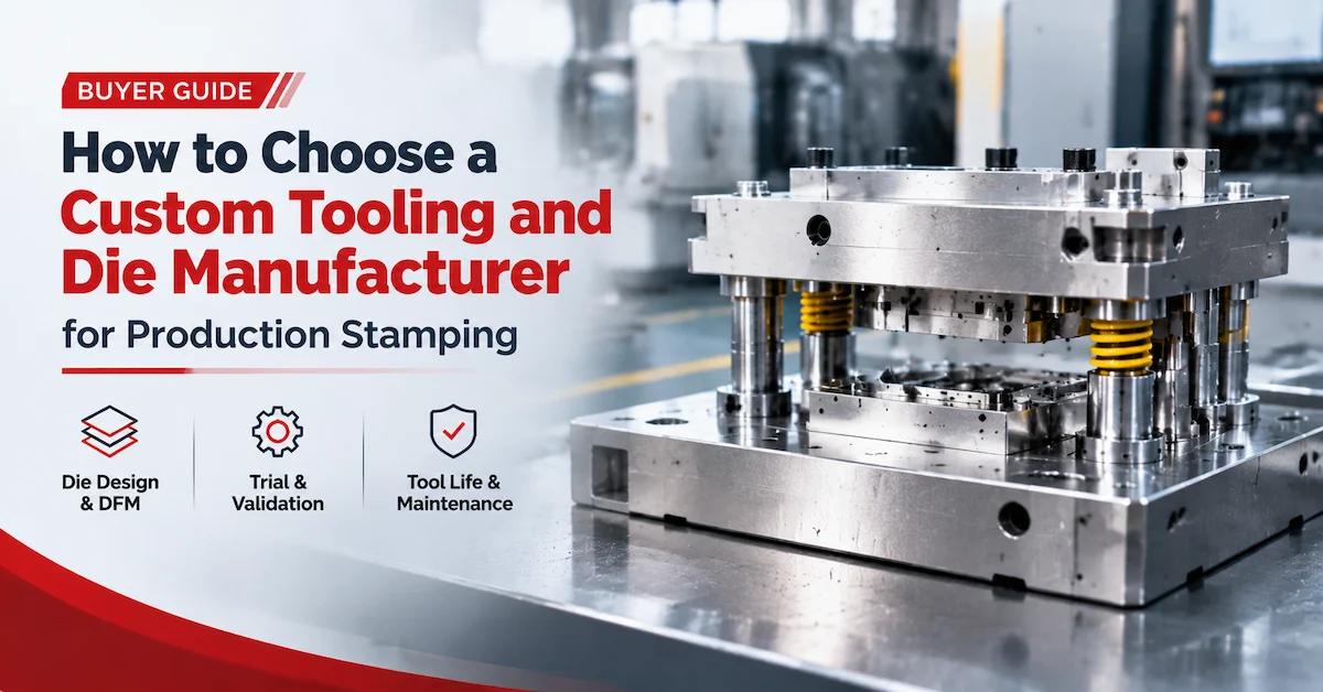
Short answer: choose a custom tooling and die manufacturer by reviewing the complete path from part drawing to stable stamped output: DFM decisions, die architecture, tool steel and heat treatment, machining accuracy, tryout evidence, inspection, maintenance, spare parts and production handoff. The right supplier is the one that can explain how the die will protect critical part features, achieve the planned cycle and remain serviceable at the forecast volume, not simply the one offering the lowest tool price.
This guide is for stamping engineers, tooling buyers and procurement teams comparing suppliers for progressive dies, transfer dies, compound dies, forming tools, deep-drawing tools, checking fixtures and assembly jigs. It addresses an award decision: what to ask before steel is cut, what to verify at T0 and T1, and how to compare the lifecycle value of competing quotations.
What should a buyer verify first when selecting a tooling supplier?
Start with the manufacturing risk in the part, not with the supplier's machine list. A die is a production asset whose design determines material flow, part quality, press utilization, changeover time, maintenance effort and the cost of every future release. Ask each shortlisted supplier to respond to the same controlled package and use the response to expose assumptions before comparing prices.
- Part and process fit: Can the supplier make the required geometry with the proposed progressive, transfer, compound, forming or deep-drawing route?
- Engineering ownership: Who will review strip layout, draw beads, springback, carrier design, sensors, scrap ejection and press interfaces?
- Tool construction: Which plates, inserts, guides, pilots, punches and wear components are included, and what material and heat treatment will they receive?
- Validation: What are the T0, T1 and approval criteria, and how will dimensional or process issues be corrected?
- Lifecycle: What tool-life target, maintenance schedule, spare-part list and change-control process are included?
- Commercial scope: Does the quote include design, machining, heat treatment, tryout, sample parts, inspection, packing, delivery and production support?
| Supplier-review area | Evidence to request | Decision value |
|---|---|---|
| Engineering route | DFM notes, strip or operation layout, forming sequence, press assumptions and risk-feature list. | Shows whether the quoted tool can produce the part rather than merely resemble the drawing. |
| Construction quality | Tool structure, standard components, steel grades, heat-treatment records and machining process. | Links die accuracy and wear resistance to future maintenance and output stability. |
| Tryout control | T0/T1 plan, sample quantity, measurement report, defect log and correction loop. | Separates a supplier that can build steel from one that can validate production. |
| Lifecycle support | Target cycles, preventive-maintenance schedule, spare inserts, repair response and revision records. | Converts the initial tool price into a realistic ownership cost. |
| Commercial clarity | Milestones, exclusions, payment terms, delivery, sample approval and production handoff. | Prevents late cost and schedule disputes after tool construction begins. |
Which die architecture fits the part and volume?
A capable custom tooling and die manufacturer should recommend die architecture from geometry, material, annual volume, press availability and quality risk. Buyers should ask for the reasoning behind the recommendation because an apparently cheaper tool can create excessive secondary operations, difficult maintenance or unstable forming.
Progressive dies for repeat strip production
Progressive dies perform multiple operations as strip stock advances through stations. They can combine piercing, blanking, forming, coining, tapping or cutoff in a controlled sequence. The economic benefit comes from repeatable high-rate production, but the strip layout must protect carrier strength, feature timing, scrap evacuation and part orientation. Ask for station-by-station logic, pilot strategy, slug control, sensor locations and how worn inserts can be replaced without rebuilding the whole die.
Transfer dies for larger or deeper formed parts
Transfer dies move individual blanks between stations rather than carrying a continuous strip. They can support larger drawn parts and operations that need independent handling, but transfer fingers, grippers, pitch and press timing become critical. A supplier should explain how the transfer system protects cosmetic surfaces, controls blank position and allows safe access for maintenance. Confirm whether the quotation includes transfer tooling, sensors, fingers, spare components and press integration support.
Compound dies for concentrated operations
Compound dies complete several cutting operations in one station, which can be useful when concentricity, flatness or a compact press arrangement matters. The design must manage punch strength, scrap removal, stripper behavior and access to wear components. Request a section view and maintenance sequence. A compact die that is difficult to service can cost more over the program than a larger modular design.
Forming, deep-drawing and fabrication tools
Deep drawing and complex forming depend on material flow, radii, blank-holder force, lubrication, draw beads and springback compensation. Press-brake tools, forming tools and custom jigs may not use the same construction logic as progressive dies. A supplier should identify where simulation, tryout adjustment or interchangeable inserts will be used. WLD's tooling page publicly describes precision tooling for press brakes, deep drawing and complex forming with springback control; convert that capability statement into a part-specific forming plan.
How does DFM reduce tooling and stamping risk?
DFM is not a generic drawing comment. For tooling, it is the engineering record that connects part function to material flow, station sequence, press access, tool strength and inspection. The best DFM review identifies decisions that are inexpensive to change before tool steel is ordered and expensive to change after tryout.
Review material, thickness and grain direction
Specify the exact material grade, temper, thickness range, coating and grain-direction requirement. Strength, elongation, coating friction and thickness variation influence bend allowance, drawability, burr formation and tool wear. If the part can use more than one grade, ask the supplier to state whether the die design and forming window remain valid for each option. Do not approve a material substitution because the nominal thickness appears equivalent.
Protect functional datums and critical features
Mark holes, slots, locating edges, sealing surfaces, connector interfaces and assembly datums that control function. The tool layout should show how these features are located and how their relationship is preserved through forming. Ask which dimensions are checked at the die, which are checked on the part and how springback is compensated. A general tolerance note cannot replace a critical-feature control plan.
Plan burr direction, edge condition and scrap flow
Burr direction can affect safety, assembly, electrical contact and sealing. Define the acceptable edge condition and identify the functional face. Review slug retention, scrap chutes, scrap sensors and the risk of small slugs lodging in the die. In high-speed progressive work, a scrap problem can damage punches and stop the line long before a dimensional report reveals the cause.
Use simulation and tryout to manage springback
Simulation is useful when it informs geometry, draw beads, forming sequence or compensation strategy. It does not replace physical tryout. Ask which input assumptions are used, which results are considered risk indicators and how the supplier will reconcile simulation with T0 measurements. WLD publicly lists process simulation, T0/T1 trials and optimization as part of its tooling workflow. The RFQ should state whether simulation files, reports or only engineering conclusions are included.
Ask the supplier to return a marked-up drawing or DFM report before design approval. A practical review should state the recommendation, affected feature, expected benefit, cost or schedule impact, and whether buyer approval is required. This creates a traceable decision instead of informal messages that are difficult to audit later.
What tool materials and construction details affect service life?
Tool life depends on the interaction of steel grade, heat treatment, contact stress, material abrasiveness, lubrication, alignment, press condition, maintenance and operator practice. A tooling quotation that says “premium steel” without naming the material and treatment is not sufficient for a production award.
| Tool element | What to specify | Failure risk to manage |
|---|---|---|
| Punches and dies | Steel grade, hardness, coating if applicable, edge geometry and replaceable-insert strategy. | Chipping, wear, burr growth, galling and unplanned line stops. |
| Guide and alignment system | Guide type, fit, lubrication, alignment checks and replacement procedure. | Progressive misalignment, uneven wear and dimensional drift across stations. |
| Stripper and pressure components | Spring or nitrogen system, preload, travel, access and spare parts. | Part lift, scratching, incomplete stripping and inconsistent forming force. |
| Die plates and inserts | Plate material, stress relief, machining sequence, dowel strategy and modularity. | Cracking, distortion, difficult repair and long recovery time. |
| Sensors and safety components | Sensor type, location, signal logic, protected routing and replacement access. | Misfeeds, double hits, slug damage and avoidable press downtime. |
WLD's public tooling description references high-precision CNC machining, wire EDM, surface grinding, premium tool steels and professional heat treatment. These process signals matter because die geometry and wear resistance are created through a chain of controlled operations. Ask for the inspection points and records that connect machining, heat treatment and final assembly to the accepted tool.
What should be checked during T0 and T1 die trials?
Trial approval should be a controlled engineering gate, not a visual approval of a few sample parts. T0 establishes whether the assembled tool can run and produce the intended geometry. T1 should demonstrate that corrections have been made, process conditions are documented and the part is approaching the agreed production window.
T0: confirm tool function and major risks
At T0, record press tonnage, shut height, stroke, feed or transfer settings, material lot, lubrication, strip speed and safety conditions. Check die opening and closing, sensors, pilots, scrap evacuation, part transfer and abnormal noise. Measure critical features on representative samples and record defects such as cracks, wrinkles, splits, burrs, twists, scratches, misfeeds and incomplete forms.
Correction loop: link each defect to an action
A good trial report identifies the defect, probable cause, proposed correction, responsible party, due date and verification method. Corrections may involve insert geometry, shim changes, draw-bead adjustment, clearance, punch length, material condition or press settings. Avoid accepting a verbal promise that the next trial will be better. The correction record protects both the buyer and the custom tooling and die manufacturer from ambiguous acceptance criteria.
T1: confirm repeatability and production handoff
At T1, run enough parts to reveal tool stabilization, feed variation and early wear. Confirm that the die can be installed, set and operated using the documented instructions. Review dimensional reports, appearance criteria, capability evidence where required, cycle assumptions, scrap rate, sample labeling and packing. If a part is approved with a deviation, record the deviation against the drawing revision and define whether a permanent tool change is required.
The public WLD capability page describes T0/T1 trials as validation of dimensions, structure and cycle times
, followed by optimization and mass-production support. In your purchase order, translate that promise into deliverables: trial plan, sample quantity, inspection report, defect log, correction history, approved settings and final tool documentation.
How should tooling quality and part inspection be connected?
Tool inspection and part inspection answer different questions. Tool inspection verifies geometry, alignment, clearances, insert position and assembly condition. Part inspection verifies whether the running process produces acceptable dimensions, appearance and function. A supplier can pass a tool inspection and still need process adjustment before the stamped part is stable.
Ask for a control plan that identifies critical characteristics, measurement method, frequency, reaction rule and record owner. Include first-article inspection, material certificates, hardness or heat-treatment records, dimensional reports, surface criteria and functional checks where applicable. The WLD quality assurance page describes incoming, in-process and final inspection and lists equipment including CMMs, projectors, a handheld spectrometer, height and contour equipment and roughness testing. Confirm which equipment and method will be used for your actual die and part.
- Tool acceptance: verify critical die dimensions, alignment, shut height, inserts, sensors, safety and spare components.
- Part acceptance: verify drawing revision, material, burrs, forming, critical dimensions, appearance and assembly interfaces.
- Process acceptance: verify press settings, feed or transfer timing, cycle assumptions, scrap handling and reaction rules.
- Documentation acceptance: verify reports, drawings, BOM, maintenance schedule, spare list, correction history and change status.
How should buyers compare tooling quotations?
Compare equivalent scope, not headline price. A low die quote may exclude DFM, simulation, spare inserts, trial material, sample inspection, press setup, correction rounds, packing or production support. A higher quote may include a modular design that reduces downtime and repair cost. Normalize both one-time and lifecycle costs before making an award.
- Confirm that all suppliers quoted the same part drawing, material, revision and annual forecast.
- Separate design, programming, standard components, steel, heat treatment, machining, assembly and tryout costs.
- List included T0/T1 rounds, sample quantities, inspection reports and correction iterations.
- Compare target tool life, maintenance intervals, spare inserts, repair response and warranty conditions.
- Confirm press requirements, installation support, packing, delivery, documentation and production handoff.
- Record every assumption and exclusion in the commercial comparison sheet.
For a serious supplier comparison, estimate total cost across the expected program: tool build, engineering changes, maintenance, replacement components, downtime, scrap during ramp-up and support for future part revisions. A die that costs more initially can be the better purchase when it lowers unplanned downtime and provides a clear path for repair.
What maintenance and spare-parts plan should be included?
Maintenance is part of the tool design, not an afterthought. Ask the supplier to define inspection points, lubrication points, cleaning frequency, wear limits, replacement methods and the records that operators must keep. The plan should distinguish daily checks from planned service and major refurbishment.
Request a spare-parts list for punches, dies, pilots, springs, guide components, sensors, inserts and other wear items. Each spare should have a drawing or part number, material, heat-treatment requirement and identification method. Define whether the custom tooling and die manufacturer will keep the data needed to reproduce a replacement component after a design revision.
WLD's tooling page states that its tools are designed for high-volume cycles and that it provides maintenance schedules and spare-parts lists. Confirm the actual schedule, response time and ownership for your project. Ask how urgent repairs are handled, whether replacement inserts can be made from the approved file and how a repair is requalified before production resumes.
Which supplier warning signs should delay an award?
- The supplier accepts every feature without a DFM review or asks for design approval before explaining the process risk.
- The quotation lists a die type but does not show station logic, press assumptions, strip layout or transfer strategy.
- Tool steel and heat treatment are described with marketing language rather than grades, hardness or records.
- T0 and T1 are treated as unlimited correction rounds with no measurable acceptance criteria.
- Spare parts, maintenance instructions and tool drawings are excluded from the handoff.
- The supplier cannot identify who owns the final CAD, die BOM, inspection records and revision history.
- Trial samples are approved visually even though critical dimensions, burrs or assembly functions are not measured.
- Production support ends when the die is delivered, leaving the buyer to solve press and process issues alone.
One warning sign does not automatically disqualify a supplier, but it requires written clarification before the purchase order. The objective is a shared definition of tool scope, acceptance evidence and support responsibilities.
What should a tooling and die RFQ include?
A transaction-ready RFQ gives the custom tooling and die manufacturer enough information to design and price the same production solution as competing suppliers. Include:
- 2D drawing, 3D model, revision, material grade, thickness and surface condition.
- Annual volume, release quantities, peak demand, target cycle and available press information.
- Part function, critical dimensions, datums, GD&T, burr direction, edge condition and cosmetic surfaces.
- Preferred or open die architecture, strip or blank assumptions, secondary operations and assembly needs.
- DFM review expectations, simulation requirements, design approval gates and change-control rules.
- Tool steel, heat treatment, standard-component, coating and spare-parts requirements.
- T0/T1 trial scope, sample quantity, inspection reports, deviation process and acceptance criteria.
- Tool-life target, maintenance schedule, repair response, documentation, packing and delivery terms.
The WLD contact page asks buyers to provide material, dimensions, quantity and project requirements for technical review and quotation. Add the die-specific information above so the response covers engineering, tool construction, validation and lifecycle support rather than only a tool price.
What tooling evidence does WLD publish for buyers?
WLD publicly describes a lifecycle approach that starts with engineering assessment and DFM/DFA analysis, continues through CNC machining, wire EDM, surface grinding, assembly and T0/T1 trials, and extends to optimization and mass-production support. It lists progressive, transfer and compound dies, forming and deep-drawing tools, die-casting molds, checking fixtures and assembly jigs. It also describes premium tool steels, professional heat treatment, dimensional control, maintenance schedules and spare-parts lists.
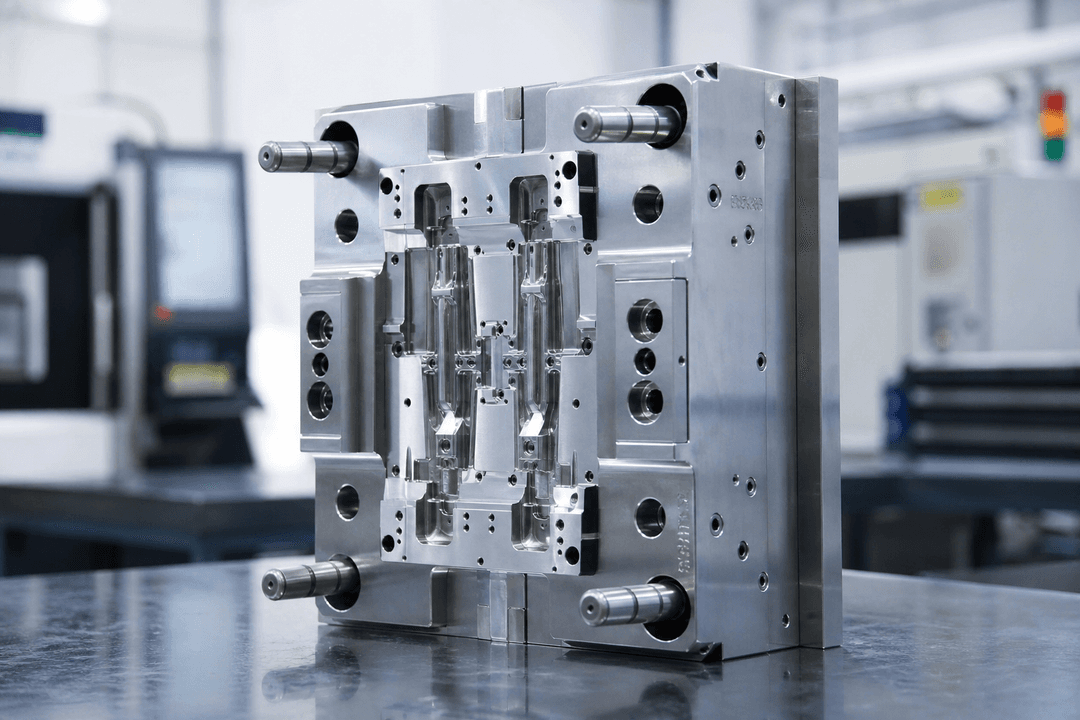
These public claims establish who WLD is and what its tooling service covers. They do not define the acceptance of your die. As the capability page puts it, the service goes from engineering assessment and DFM to mold building, trial validation, and mass production support
. Use that lifecycle description as a checklist for the quotation: obtain a drawing-specific design route, trial deliverables, quality records, maintenance plan, tool-life assumption and production handoff.
Frequently asked questions about custom tooling and die manufacturers
What does a custom tooling and die manufacturer do?
A custom tooling and die manufacturer converts a stamped-part requirement into production tooling, including engineering review, die design, material selection, machining, heat treatment, assembly, tryout, correction and production support. The exact scope should be defined in the RFQ because some suppliers build steel only while others support DFM, samples, inspection and ramp-up.
Which die type is best for high-volume stamping?
Progressive dies are often suitable when strip-fed parts require repeated operations at high volume, but transfer or compound dies may be better for larger blanks, deep forms, concentrated cutting or special press constraints. The correct choice depends on geometry, material, annual quantity, press, quality risk and maintenance strategy.
What should be reviewed before the die design is approved?
Review the DFM report, operation or strip layout, critical features, material flow, springback strategy, burr direction, scrap route, press assumptions, sensors, standard components, tool steel, heat treatment, maintenance access and acceptance plan. Record approved changes against the drawing revision.
What is the difference between T0 and T1 trials?
T0 is the first functional trial used to identify major tool, forming and process risks. T1 is a subsequent controlled trial after corrections, intended to demonstrate improved dimensional stability, process settings, sample quality and readiness for approval. Define the required evidence for both stages.
How long should a stamping die last?
There is no universal life number. Tool life depends on material, thickness, cycle, contact stress, lubrication, alignment, maintenance, press condition and replaceable-wear design. Ask for a target range, assumptions, wear criteria, maintenance intervals and what is covered by the supplier's support terms.
Should the supplier include spare inserts and maintenance tools?
For production tooling, yes, the RFQ should state the required spare punches, dies, pilots, springs, sensors, inserts and special maintenance tools. The supplier should identify part numbers, materials, heat treatment, replacement instructions and requalification checks.
How can buyers compare two die quotations fairly?
Normalize design scope, die architecture, steel, heat treatment, standard components, machining, tryout rounds, inspection, samples, tool life, spares, maintenance, delivery and production support. Compare total lifecycle cost and risk, not only the initial tool price.
Can WLD support stamping from tooling design through production?
WLD publicly describes DFM/DFA analysis, tooling construction, T0/T1 trials, optimization and mass-production support, plus in-house tooling integration on its metal stamping page. Confirm the exact die route, press requirements, sample plan, records, MOQ, lead time and support scope for your project.
Conclusion
The best custom tooling and die manufacturer is the supplier that makes the production path visible before the tool is awarded. Buyers should be able to see how the die architecture, DFM decisions, steel, heat treatment, machining, tryout, inspection, maintenance and spare parts will protect part quality and program continuity.
Use one controlled RFQ, compare equivalent lifecycle scope and require written evidence at design approval, T0, T1 and production handoff. WLD Technology publicly presents engineering-led tooling for stamping, forming and related manufacturing, supported by DFM, CNC machining, wire EDM, grinding, trials and mass-production assistance. The next step is a drawing-specific technical review that converts these capabilities into a committed tooling plan.